Two Phase Flow and Magnets for Gas

I am going to do my very best in this Blog not to come across as a cynic when looking at how products for process steam are sold. One of the phrases I hear from customers who have had presentations on some types of condense removal devices is two-phase flow. For those that aren’t fully aware of what two-phase flow is, it is a liquid and a gas flowing within the same pipework system. In the case of process steam, it is a key element of sizing a condense return system and is also known as multiphase flow. The fact that two-phase flow occurs within a steam system has been used to sell products that are a pipe or disc with a hole in it and are competing with steam trap technology that is tried and tested and in most cases has improved over the last 50 years.
Two-Phase Flow and Fixed Orifice Condense Removal
A fixed orifice must be highly engineered and correctly sized to achieve a limited range of condense removal. If process conditions achieve a fixed flow rate unaffected by winter and summer steam loads, changes to steam flow due to temperature control applications and steam locking are not present, then you have the perfect conditions for an orifice device to remove condense from your heat exchanger.
Orifice devices are sized on the maximum condensing flow from a heat exchanger or line drain; some manufacturers of these devices point out when they are honest, that steam will leak when condensing is at its lowest flow rate.
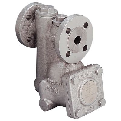
One of the orifice trap manufacturers we have come across also states that due to the two-phase flow within the steam system, their devices can leak around 1kg/hr of steam. In truth, the same applies to thermodynamic steam traps a technology which is almost as old as orifice condense removal. If you compare this to a TLV free float line drain steam trap, the leak rate on this type of trap is 0.05kg/hr. A quick comparison over 12 months will tell you all you need to know.
1kg/hr x 10 hours per day = 10kg Day – 0.05kg/hr x 10 hours per day 0.5kg Day
10kg x 5 working days = 50kg week – 0.5kg x 5 working days = 5kg week
50kg x 50 working weeks = 2,500kg Year – 5kg x 50 working weeks = 250kg Year
This doesn’t sound like a great deal till you consider that if you have 10 of these devices on a site, that is the possibility of 25,000kg a year in lost steam. If you then consider that orifice condense removal devices wear like any other steam trap, these steam losses may increase.
Two-Phase Flow why a Mechanical Steam Trap

Sizing a mechanical steam trap based on differential pressure is a straightforward process, whether the trap is a TLV-free float or a budget float trap. If the maximum or average load is calculated from a heat exchanger then the required steam trap can be sized. Free Float/Float Trap technology will provide condense removal for start-up loads and then function across the full range of minimum and maximum loads. On the outlet side of a steam trap, it is essential that the condense return is correctly sized and this can be achieved by visiting the TLV Calculator; these calculations are based on two-phase flow within a condense return main.
Because a free float/float trap has a varying orifice, condense will be removed efficiently even when the flow rate is at its minimum or maximum or anywhere in between. In the case of Free Float steam traps the system has an additional barrier to leaking steam in the condense itself. This is because a TLV Free Float steam trap relies on the buoyancy of the float to seat; achieving a water barrier that is always present within the trap.
Two-Phase Flow Myths and Legends
For many years, we saw a seller of orifice technology showing a video during their presentations of a TLV Free Float steam trap leaking steam. If you watch this video more closely you will see that this is in fact flash steam and within an enclosed system correctly sized this may never occur; there are however instances where a vacuum is present that does cause flash steam, to discuss resolving this contact our technical sales team.
Other issues that can be associated with the orifice devices are the orifice blocking up particles from the system, and requiring regular checks of the inline strainer or integrated strainer. TLV Free Float steam traps have a large integral strainer which can be up to eight times the surface area of an inline strainer.
Even if the outlet of a TLV free float steam trap is blocked, in a rare event it is easily accessible via a plug underneath the steam trap; sealed with an integral teflon gasket which can be re-used. Unblocking an orifice could involve removing the entire device from the system to clean, all TLV free-floats can be cleaned in situ; making maintenance an easier task.
If you have orifice devices installed on your site where varying loads occur, we would be happy to offer a correctly sized TLV free float steam trap on a trial. This could be from one month to three months, running on the same process; if the TLV free float achieves better results we invoice for the trap, if not then the trap can be returned. Please contact us to discuss and make arrangements with our sales team.
Magnets for Gas
Besseges (Valves, Tubes & Fittings) Ltd does not offer technology we do not believe in on solutions for process steam. In the case of orifice technology if we came across a process that was completely suitable and would improve the process outcomes for a business; we would recommend it. In our present experience within the industries we have worked in this has not yet occurred.
As for magnets for gas, we have seen no evidence that convinces us that the technology offers anything positive to our customer base. Our comments section is always open to those who want to reply to our Blogs, so please feel free to do so.
Get started in seconds!
Save your details, view past orders, and enjoy a faster checkout every time.