Installing a Pressure Reducing Valve for Steam

Installing a pressure-reducing valve for steam is as important as sourcing the correct pressure-reducing valve because if your installation is poor or incorrect the heat exchanger you’re supplying won’t work to its full capacity. What you have to remember is the majority of good quality pressure-reducing valves are precision instruments manufactured to the highest standard although some out there claim this but aren’t. From a personal perspective on pressure-reducing valve technology if what is in front of you hasn’t seen original design flaws altered or changed then it won’t function to your or anyone else’s satisfaction.
A good quality product will stand out as soon as you take it out of the box and within the box you should find a clear guide to installing a pressure-reducing valve for steam or if that isn’t available an excellent technical team to guide you through the process. Here at Besseges (Valves, Tubes & Fittings) Ltd, we can provide all the assistance you need having been involved in guiding many customers through the process of installing a pressure-reducing valve for steam, our technical team can be contacted during the working day and for our account customers even out of working hours especially when an installation is being completed during a shutdown or over the weekend.
For more information on installing a pressure-reducing valve for steam contact our technical sales team or continue reading.
Installing a Pressure Reducing Valve for Steam, Correct Sizing
The first part of sizing a pressure-reducing valve is to ascertain the capacity of the heat exchanger or heat exchangers for the reduced line services. This can be achieved by either discussing this with the OEM, considering the line sizing already installed as from this you can work out the maximum capacity of the pipework or calculate the steam load based on the process information.
For example, if a tank of fluid is to be heated to a required temperature; the total contents in litres, then use the specific heat value (the amount of heat per unit mass required to raise the temperature by one degree Celsius), differential temperature (the difference between the initial temperature and the temperature required) and finally the specific enthalpy (total energy in a system due to pressure and temperature per unit of mass in that system) of steam at a given pressure.
The example below is based on 1000 litres of water heated to 85°C from 15°C in one hour using steam at 2 barg answering Kilograms per hour.
1000 x 4.186 x 70 ÷ 2163 = 136kg/hr
Next, you must consider that the start-up load will be higher than the average working load of 136Kg/Hr and we usually allow for another 20% of steam available for the process, so in this case we would size the pressure-reducing valve at a minimum of 163Kg/Hr. In the case of our own TLV pressure-reducing valves the capacities can be found on the datasheets, please contact us to arrange for a copy to be sent to you depending on the type of pressure-reducing valve required. If you would prefer some assistance in sizing any type of steam valve or steam trap, please contact our technical sales team as we are always happy to help.

Installing a Pressure Reducing Valve for Steam, Best Practice
When installing a pressure-reducing valve for steam it is important to realise that how the installation is put together is as important as the correctly sized valve. If you take the time to size up the valve to suit your steam flow, even add a little more capacity for the future and then cram the valve into the smallest space possible you have just wasted your time. What follows are generally what TLV specify for their pressure-reducing valves but as the principles of all other pressure-reducing valves for steam are similar in operation, common sense would suggest they would be subject to the same constraints so we would recommend this for installing most pressure-reducing valves for steam.
When you are installing a pressure-reducing valve for steam it is our viewpoint that the following guidelines should be adhered to:
- Only ever use eccentric reducers when installing a pressure-reducing valve, the use of concentric reducers will increase the probability of water hammer problems that will affect the service life of a pressure-reducing or control valve.
- The steam line before the inlet eccentric reducer should be clear of outlets, valves, strainers and elbows to a distance of 10 pipe diameters.
- The steam line following the outlet eccentric reducer should be clear of outlets, valves, safety valves and elbows to a distance of 15 pipe diameters.
- The inlet steam line should be sized for the correct steam flow at the steam main pressure.
- The outlet steam line should be sized for the reduced steam pressure ensuring the full capacity of the correctly sized pressure-reducing valve is met.
- Inline Strainers (not required for the installation of a Cospect PRV) should be installed in the horizontal plane, vertically installed strainers will increase the likelihood of water hammer problems and reduce the service life of a pressure-reducing or control valve.
- Safety Valves where required should be sized to the maximum steam load at full steam main pressure
- Stop Valves should be installed before and after the pressure-reducing valve, double block and bleed are recommended for new installations to meet HSE guidelines.
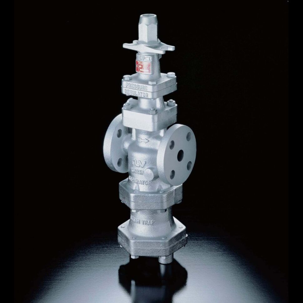
- If a standard pressure-reducing valve for steam is being installed a separator or dirt pocket complete with a steam trap set is recommended prior to the first stop valve, this does not apply when installing a TLV Cospect as the unit has a built-in steam separator and steam trap.
- For applications where the pressure-reducing valve is supplying a single heat exchanger and is dead-ending, the line should be isolated when not in use or if this is not possible a relay point dirt pocket should be fitted prior to the heat exchanger. Dead-ending can result in the pressure creeping, causing the safety valve to operate.
Installing a Pressure Reducing Valve for Steam, Conclusion
The information we have provided covers most bases when installing a pressure-reducing valve for steam, the attached sketch is a guide to completing a typical install and as one of the North of England’s leading process steam specialist suppliers’ we are always happy to aid with the installation of our products. We have worked on many installations over the past two decades with contractors and end users alike, ensuring that they have the right products to complete the work at hand. Please contact us for more information by clicking the highlighted links or by talking to us directly on 0161 343 2225 for UK-based businesses; we look forward to hearing from you.
Get started in seconds!
Save your details, view past orders, and enjoy a faster checkout every time.
